🔧 Mini Project Task 1 — Building and Testing the Edge Device
Note
Before starting, make sure you have completed the Getting Started guide (IDE setup, forking, cloning, adding a course educator as a collaborator, and opening firmware/ in PlatformIO).
1.0 — 🌿 Create a branch for this task
- On GitHub, in your fork, go to the branches page and click
New branch. Name ittask-1, create it frommain, and clickCreate new branch. - Open your cloned repository in VSCode.
- In a terminal, run
git fetchto make VSCode aware of the new branch. - Check out the new branch:
- On GitHub, in your fork, click on
Pull requests→New pull request. Setbase: mainandcompare: task-1. The description box will be pre-filled from the pull request template — skim it now, you'll fill it in as you go. - Click the dropdown arrow on the
Create pull requestbutton and chooseCreate draft pull requestinstead.
All the work for this task should be committed to the task-1 branch.
What to put in the pull request description
- Title:
Task 1 — Building and testing the edge device - Feature purpose: Build the edge device's core sense/actuate loop — read the push button, drive the LED — and verify it with a simple serial "reset" handshake, the same pattern every later task will reuse with a different reset trigger.
- Feature architecture: An Arduino MKR WiFi 1010 wired to a push button (pin D2, input) and an LED (pin D3, output).
loop()polls the button; once pressed,handShakeProtocol()blocks until it receives a reset signal — here, an integer typed into the Serial Monitor — then blinks the LED that many times before turning it back on. - Feature interfaces: Digital I/O pins D2 (button) and D3 (LED); the Serial Monitor over USB, standing in for the network/cloud acknowledgement used in later tasks.
- Test plan: Manual hardware test — confirm the LED is on by default, turns off on button press, and blinks N times then turns back on when N is entered in the Serial Monitor (see 1.3).
- Implementation roadmap: e.g. wire the hardware → implement
handShakeProtocol()→ build & upload → manually verify against 1.3.
Note
For this mini project, we're giving you this breakdown to get you familiar with what "planning a feature" looks like before you touch any code. For your group project, nobody will hand you this plan — working out the purpose, architecture, interfaces, and test plan for each feature is part of the planning work you'll be doing yourselves.
1.1 — 🔨 Building the edge device
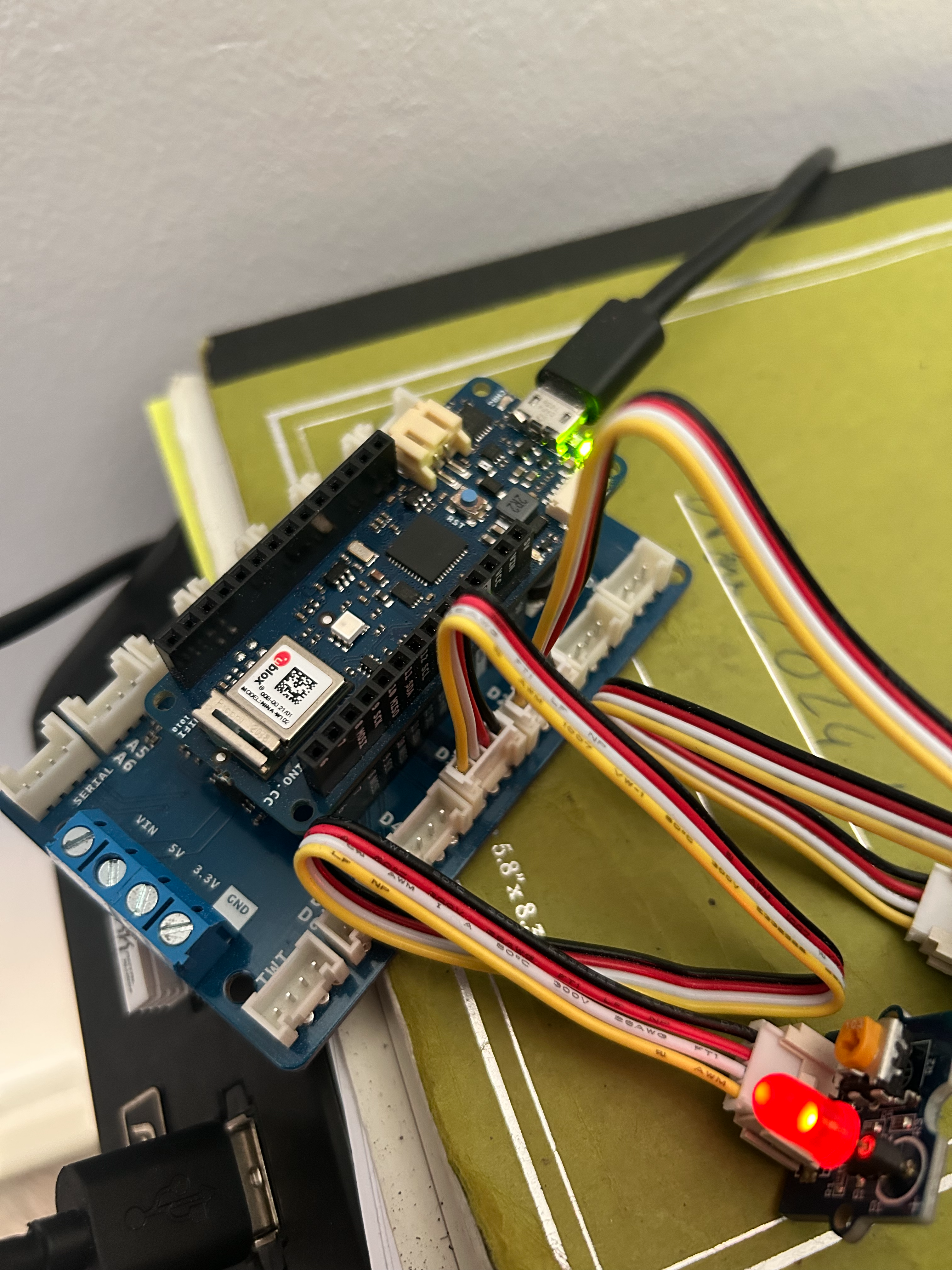
- Connect the Arduino MKR WiFi 1010 to the MKR Connector Carrier.
- Connect the LED module to port D3 of the MKR Connector Carrier.
- Connect the Push Button module to port D2 of the MKR Connector Carrier.
Warning
Make sure to correctly orient the connectors.
1.2 — ⬆️ Write and upload the firmware to the edge device
Event logic implemented in task 1:
sequenceDiagram
    box Edge Device
        participant PB as Push Button
        participant LED as LED
        participant MCU as Arduino (Firmware)

    end
    participant SM as Serial Monitor


    PB->>MCU: Button pressed
    MCU->>LED: Turn OFF
    MCU->>SM: Print "Waiting for reset..."

    SM->>MCU: Send integer (e.g. 3)

    MCU->>LED: Blink N times\n(N = received integer)

    MCU->>LED: Turn ON
MCU->>SM: Print "Reset received"- In VSCode, click on the Explorer tab, and double click on the file
firmware/src/main.cppto open it. - Read the code, and familiarise yourself with how it implements the event logic illustrated above.
- In
main.cpp, implement the functionhandShakeProtocol()so that when triggered:- It waits for an integer from the Serial monitor.
- When received, it runs the function
ledBlinkPaternusing the integer as its argument. - When
ledBlinkPaternis done running, it setsresetReceivedto 0 and it turns the LED back on.
- In the PlatformIO tab, in
general, click onBuild. Check the terminal for errors. - In the PlatformIO tab, in
general, click onUpload and Monitor.
1.3 — ✅ Test the edge device
Verify the following:
- By default, the LED is on.
- When pressing the button, the LED turns off and stays off.
- When entering an integer in the serial monitor, the LED blinks (3 times if you entered 3...), and then turns back on.
1.4 — 🔀 Submit the task for review
- Commit and push your changes to the
task-1branch — they show up automatically in your draft pull request. - Finish filling in the pull request description from the template (purpose, architecture, interfaces, test plan, roadmap).
- On the pull request page, click
Ready for reviewto take it out of draft. - Request a review from the course educator you added as a collaborator in Getting Started (click the gear icon next to
Reviewers). - Once the pull request is approved, click
Merge pull request→Confirm merge. - On GitHub, in your fork, click on
Releases(in the right sidebar of the repository home page) →Create a new release. ClickChoose a tag, typev1.0.0, and clickCreate new tag: v1.0.0 on publish. Make sureTargetis set tomain, then clickPublish release.
💡 Solutions for Task 1
firmware/src/main.cpp:
#include <Arduino.h>


// Pin definitions
const int buttonPin = 2;     // the number of the pushbutton pin
const int ledPin =  3;      // the number of the LED pin

// Status variables
int buttonState = 0;         // variable for reading the pushbutton status
int resetReceived = 0;       // variable for reading the reset status


// Function prototypes
void ledBlinkPatern(int pattern);
void handShakeProtocol();


// The setup function runs once when you press reset or power the board
void setup() {
    // initialize serial communication.
    Serial.begin(9600);
    // initialize the LED pin as an output.
    pinMode(ledPin, OUTPUT);
    // initialize the pushbutton pin as an input.
    pinMode(buttonPin, INPUT);
    // make sure the LED is on at the start
    digitalWrite(ledPin, HIGH);

}

// The loop function runs over and over again forever
void loop() {

    buttonState = digitalRead(buttonPin);

    if (buttonState == HIGH && resetReceived == 0) {
        Serial.println("Button pressed, waiting for reset...");
        resetReceived = 1;
        digitalWrite(ledPin, LOW);
    }

    if (resetReceived == 1) {
        handShakeProtocol();
        delay(1000); // Add a delay to prevent the loop from running too fast after the handshake protocol is complete
    }


}


void ledBlinkPatern(int pattern) {
    /*************************************************************
    * This function is used to show the status of the LED.
    *
    * The pattern indicates how many times the LED will blink.
    * For example, if the pattern is 3, the LED will blink 3 times.
    **************************************************************/
    Serial.print("Status received:");
    Serial.println(pattern);
    for (int i = 0; i < pattern; i++) {
        digitalWrite(ledPin, HIGH);
        delay(500);
        digitalWrite(ledPin, LOW);
        delay(500);
    }
}

void handShakeProtocol() {
    /*************************************************************
    * This function is used to implement the handshake protocol between pressing the button and the reset of the LED.
    *
    * When the button is pressed, the LED will turn on and stay on until the reset is received.
    * Once the reset is received, the LED will turn off and the system will be ready for the next button press.
    * In task 1, the reset is triggered by waiting for an integer pattern to be sent through the serial monitor.
    * In task 2, the reset is triggered by connecting to an external server to check that the device is connected to the internet.
    * In task 3, the reset is triggered by waiting for an MQTT message that aknowledges that the device is connected to the MQTT broker.
    * In task 4, the reset is triggered by waiting for an MQTT message that sends a specific command to the device based on administrative rules defined in the cloud.
    **************************************************************/

    // TODO: YOUR CODE HERE
    if (Serial.available() > 0) {
        int pattern = Serial.parseInt(); // read the pattern from the serial monitor
        ledBlinkPatern(pattern); // blink the LED according to the received pattern

        resetReceived = 0; // reset the reset status
        digitalWrite(ledPin, HIGH);
        Serial.println("Reset received, LED is ON, waiting for button press...");
    }
}